Page 3 of 4
Re: checking valve clearance
Posted: Mon Nov 04, 2013 5:28 pm
by Tapio
Corvus wrote:
That's almost what I'd imagined. Flat underneath, but I'd imagined the inside might be spherical. I thought that if the inside were flat, what has been gained? Perhaps the component doesn't serve the purpose I'd imagined.
I think so too. Something like this, maybe?

Re: checking valve clearance
Posted: Mon Nov 04, 2013 6:03 pm
by Corvus
Tapio wrote:Corvus wrote:
That's almost what I'd imagined. Flat underneath, but I'd imagined the inside might be spherical. I thought that if the inside were flat, what has been gained? Perhaps the component doesn't serve the purpose I'd imagined.
I think so too. Something like this, maybe?
I'm guessing exactly like that. But someone will know for sure.
Posted: Mon Nov 04, 2013 6:16 pm
by Corvus
SP250 wrote:Good points well made.
However the "elephants feet" if anything like the ones I have seen in other engines (first one a Triumph Trident in the 70's) should rotate in operation.
In addition they move in an arc centered on their pivot so the action of pressing down the valve stem moves them in a line of contact "wiping" across the top of the valve stem. Combined with their slow rotation the wiping action means that a hollow doesn't get worn and should wear evenly and stay flat.
Any high mileage bikes would show the problem and be reported on here.
Thanks.
Yep, I understand what you're saying and it is likely a hollow doesn't occur. Although, looking at tapio's photo, the EF does appear to be considerably larger in diameter than the valve stem. So large as to make one question as to whether the wiping action you describe, essentially created by the arc of movement of the rocker and the slow rotation of the EF, will actually cover the entire surface area of the EF.
Regarding reporting the problem, they won't know it exists (it probably doesn't!) if they only use feeler gauges. Fair point? Although someone will have stripped one down.
Cheers.
Posted: Thu Nov 07, 2013 4:03 pm
by Tapio
SP250 wrote:Good points well made.
However the "elephants feet" if anything like the ones I have seen in other engines (first one a Triumph Trident in the 70's) should rotate in operation.
I understand that the EF is free to rotate, but is there something in the design
forcing it to do so? Or is it just that the EF can rattle around when valves are closed?
And, chances are, it has rotated a little in between every valve closing?
Posted: Thu Nov 07, 2013 6:24 pm
by SP250
Tapio
In some engines the EF is slightly offset to the centreline of the valvestem but only by 0.5 to 1.0mm.
This can impart a slight side loading to encourage the EF to rotate slightly between each contact as you said.
Sometimes I assume it is the "rattling around" when there is the clearance gap which allows it to rotate.
Posted: Thu Nov 07, 2013 6:50 pm
by Corvus
I once had the misfortune to have owned an Enfield 350 bullet.
The valve clearance was zero. The clearance was adjusted at the bottom end of the pushrods, just above the tappets. You could actually run the engine (on the stand) with the little square access cover removed and see the clearance increase (and the clatter) as the engine warmed up. As soon as a clearance appeared, as the engine warmed, you could see the tappets being "flicked" around. I wasn't sure how this was achieved, but I guessed something similar to what sp250 has described. I assumed it was deliberate!
As long as the elephants feet are free, in the case of our boxer, I'm confident I could set the clearance using a DTI. And my fingers and eyes.
Posted: Fri Nov 08, 2013 6:17 pm
by Tapio
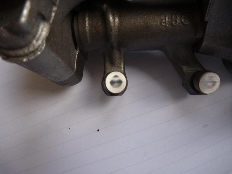
On most (if not all) pushrod engines, the lifters are sitting a little bit offset from the cam lobe center. I have exaggerated it in my CAD model.

Posted: Sat Nov 09, 2013 11:53 pm
by Tapio
Comments on my pic above: don’t know if it was understood what i meant with it. Since the center of the lifter is offset from the center of the cam lobe, when the cam lifts the lifter, it is forced to rotate. This makes for an even wear on the lifter. Also, the bottom of the lifter isn’t flat, but a bit rounded, with a really big radius.
Posted: Sun Nov 10, 2013 8:42 am
by Corvus
Tapio wrote:Comments on my pic above: don’t know if it was understood what i meant with it. Since the center of the lifter is offset from the center of the cam lobe, when the cam lifts the lifter, it is forced to rotate. This makes for an even wear on the lifter. Also, the bottom of the lifter isn’t flat, but a bit rounded, with a really big radius.
Thanks tapio.
Yeah, that makes sense.
Perhaps the EF also has a radius on the bottom surface? If so, any wear would tend to make it flat as opposed to concave.
How are such curved surfaces ground? Is the work piece moved around whilst being ground, to achieve the desired result?
Posted: Sun Nov 10, 2013 5:28 pm
by boxerscott
[quote="Herb"]Deleted my previous post. Must remember not to post while under the influence. Especially on technical posts
. I have no will power under the influence, but am sober now and can control myself from posting on this. Well maybe not, Wot on earth do you expect to find under the head covers? Yorkshire puddings?

Posted: Sun Nov 10, 2013 7:14 pm
by nab 301
Posted: Sun Nov 10, 2013 10:23 pm
by Corvus
Thanks for the photos.
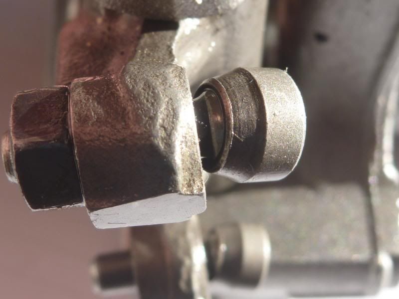
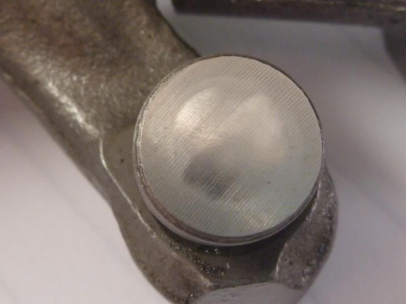
Well, judging by the photos, we can see that the wear patch goes nowhere near the edge of the EF base. Whether it is worn concave or flat (or is convex) I can't tell. But if it is concave then the feeler gauge won't probably give an accurate measurement, I assume. The original machining marks are parallel, suggesting the surface starts out perfectly flat, but of course, I could be completely wrong.
It looks as though the end of the screw is spherical and the EF possibly crimped on?
Cheers
Posted: Mon Nov 11, 2013 8:18 am
by oyster
The end of the screw is spherical, so the captive cup must have some crimp to hold it in place. The wear on the base of the cup reflects the dimensions of the top of the valve. The machining marks across the face of the base of the cup are still apparent in the worn contact area, so I suspect the amount of concave wear is not measurable, or relevant, with a feeler gauge.
Posted: Mon Nov 11, 2013 1:11 pm
by Droptarotter
The sole of the foot is flat to give as large a contact patch with the top of the valve.
Cheers
Posted: Mon Nov 11, 2013 5:11 pm
by Corvus
oyster wrote:The end of the screw is spherical, so the captive cup must have some crimp to hold it in place. The wear on the base of the cup reflects the dimensions of the top of the valve. The machining marks across the face of the base of the cup are still apparent in the worn contact area, so I suspect the amount of concave wear is not measurable, or relevant, with a feeler gauge.
Struggling to fault your logic.